Thin Film High Frequency Resistors

High Frequency Resistors
Passive Plus’ High Frequency thin-film resistors are designed to operate over a frequency range extending from DC to as high as 67 GHz. Precision laser trimming ensures the tight tolerances needed to achieve superior performance at ultra-high frequencies. These resistors are wire-or-ribbon-bondable, or can be used in a flip-chip configuration.
| Operating Frequency | DC to 67 GHz |
| Operating Temperature Range | -55°C to +150°C |
| Resistive Material | Tantalum Nitride (TaN) |
Applications
Optical Transceiver Modules
Broadband Receiver
TOSA/ROSA
Broadband Test Equipment
Low Noise Amplifiers
MMIC Amplifiers
5G
Markets
Opto-Electronics
Telecom
Broadband
Military
Satellite Communication
High Frequency Resistors
Part Numbering
Example PPI Part Number: R35-1209BB50R00FR1QC
| High Frequency Resistor | Substrate | Case Size | Resistance Value | Tolerance | Metallization | Style | TC | Power Handling |
| R | 35 | 1209BB | 50R00 | F | R | 1 | Q | C |
| Resistor | 35 = Alumina (Al₂O₃) | 1209BB = (0.012″ x 0.009″) | 50R00 = 50Ω | F = ±1% | R = For Soldering | 1 = Recessed Pad | Q = ±150ppm/°C | C = 50mW |
| See Table | See Table | See Table | See Table | See Table | See Table | See Table | See Table |
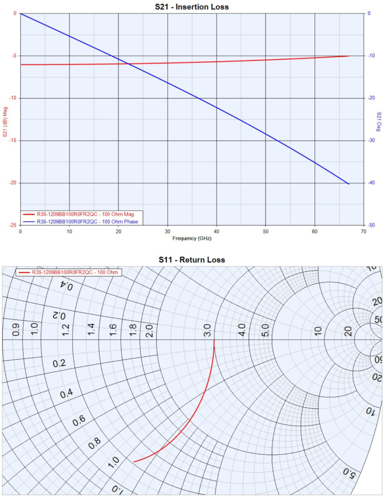
Example PPI Part Number: R35-1209BB100R0FR1QC
| High Frequency Resistor | Substrate | Case Size | Resistance Value | Tolerance | Metallization | Style | TC | Power Handling |
| R | 35 | 1209BB | 100R0 | F | R | 1 | Q | C |
| Resistor | 35 = Alumina (Al₂O₃) | 1209BB = (0.012″ x 0.009″) | 100R0 = 100Ω | F = ±1% | R = For Soldering | 1 = Recessed Pad | Q = ±150ppm/°C | C = 50mW |
| See Table | See Table | See Table | See Table | See Table | See Table | See Table | See Table |
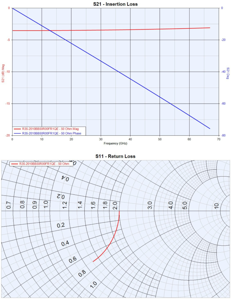
Example PPI Part Number: R35-2010BB50R00FR1QE
| High Frequency Resistor | Substrate | Case Size | Resistance Value | Tolerance | Metallization | Style | TC | Power Handling |
| R | 35 | 2010BB | 50R00 | F | R | 1 | Q | E |
| Resistor | 35 = Alumina (Al₂O₃) | 2010BB = (0.020″ x 0.010″) | 50R00 = 100Ω | F = ±1% | R = For Soldering | 1 = Recessed Pad | Q = ±150ppm/°C | E = 100mW |
| See Table | See Table | See Table | See Table | See Table | See Table | See Table | See Table |
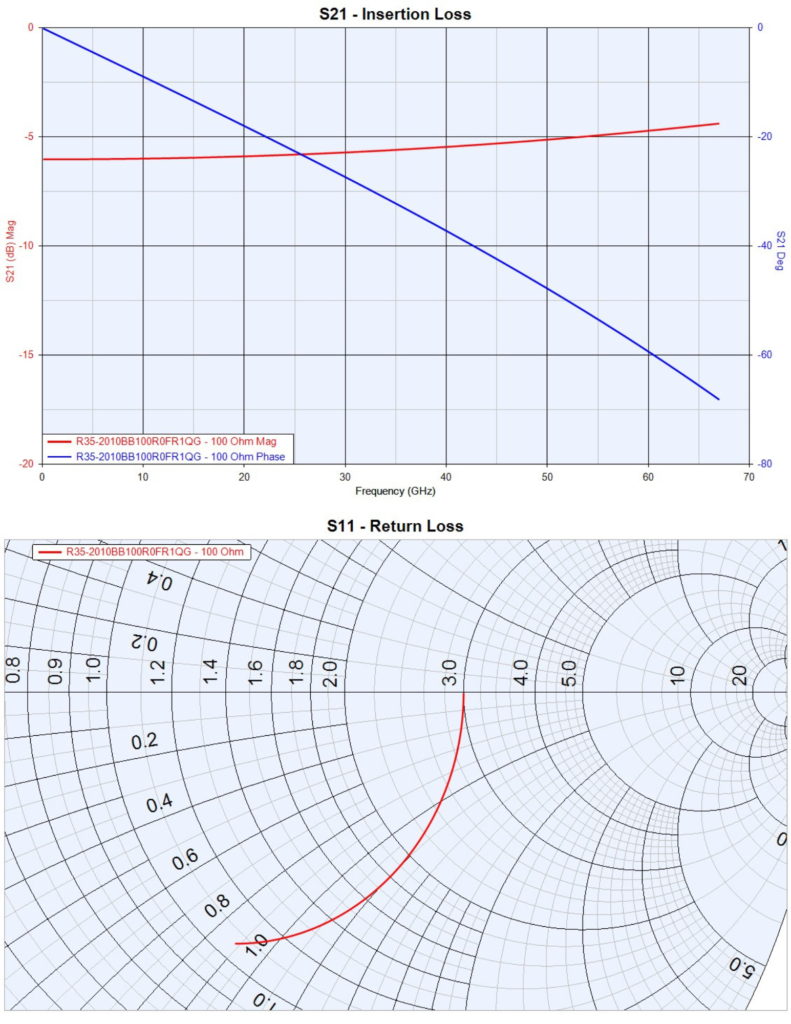
Example PPI Part Number: R35-2010BB100R0FR1QG
| High Frequency Resistor | Substrate | Case Size | Resistance Value | Tolerance | Metallization | Style | TC | Power Handling |
| R | 35 | 2010BB | 100R0 | F | R | 1 | Q | G |
| Resistor | 35 = Alumina (Al₂O₃) | 2010BB = (0.020″ x 0.010″) | 100R0 = 100Ω | F = ±1% | R = For Soldering | 1 = Recessed Pad | Q = ±150ppm/°C | G = 250mW |
| See Table | See Table | See Table | See Table | See Table | See Table | See Table | See Table |
Substrate Materials
| Code | Material | Thickness | Surface Finish | Dielectric Constant (@ 1MHz) |
Coefficient of Thermal Expansion (x10⁶/°C) |
Thermal Conductivity (W/m*K) |
| 35 | Alumina (Al₂O₃) |
0.005″ – 0.010″ | 2μ” – 3μ” | 9.9 | 7 (25°C to <300°C) |
26.9 |
Case Size
Resistance Value
Tolerance
| Case Size | 1209 | 2010 |
| Length | 0.012″ ± 0.001″ (0.305mm ± 0.051mm) |
0.020″ ± 0.002″ (0.508mm ± 0.051mm) |
| Width | 0.009″ ± 0.001″ (0.229mm ± 0.051mm) |
0.012″ ± 0.001″ (0.305mm ± 0.051mm) |
| Thickness | 0.005″ ± 0.001″ (0.127mm ± 0.051mm) |
0.012″ ± 0.001″ (0.305mm ± 0.051mm) |
| Code | Resistance Value |
| 50R00 | 50Ω |
| 100R0 | 100Ω |
| Code | Tolerance |
| F | ±1% |
Metallization
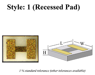
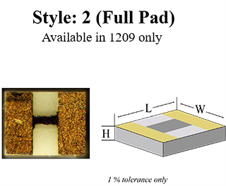
Resistor Style
| Code | Metallization | Attachement Options |
| A | TaN/Pd/Au | For Wirebonding |
| R | Ti/Pt/Au | For Soldering |
Temperature Coefficient
Power Handling
| Code | TC |
| Q | ±150 ppm/°C |
| Code | Watts | Available In |
| C | 50 mW | 1209 50Ω 1209 100Ω |
| E | 100 mW | 2010 50Ω |
| G | 250 mW | 2010 100Ω |
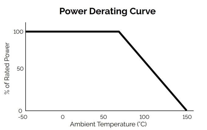
Full power up to 70°C
Derated linearly to zero power at 150°C
Simulated Test Conditions/Pad Dimensions/Dielectric
Packaging
Modelithics calculated data for 50 Ohm and 100 Ohm resistors from 0.1 to 67.0 GHz on 4 mil Rogers 4350B, Dielectric constant = 4.15. The pad dimensions used to develop the datasheet plots were: Length = 4.0 (0.102), Width = 10.0 (0.254), Gap = 5.0 (0.127). Units in mil (mm). Reference planes were at the pad edges.
Modelithics calculated data for 50 Ohm and 100 Ohm resistors from 0.1 to 67.0 GHz on 4 mil Rogers 4350B, Dielectric constant = 4.15. The pad dimensions used to develop the datasheet plots were: Length = 4.0 (0.102), Width = 10.0 (0.254), Gap = 13.0 (0.330). Units in mil (mm). Reference places were at the pad edges.
| Code | Style |
| W | Waffle Pack (Standard) |
Contact PPI for additional packaging options.
Performance Curves – Insertion and Return Loss Charts
Passive Plus offers a comprehensive range of Thin Film Components, designed to meet the diverse needs of the engineering community. PPI Thin Film Components are Made-to-Order and customized to specific applications. Offering precision, reliability, and customization options that cater to your unique requirements.
PPI Thin Film Components deliver tight tolerances, precision, and reliability for any engineering project. Explore each Thin Film type to determine the perfect fit for your application or contact PPI (sales@passiveplus.com) and our team can work with you to determine the best solution.
Once these specifications are confirmed, PPI will then supply the customer with a Spec Sheet with pricing and delivery options.
Please contact PPI directly at 631-425-0938 or by email at sales@passiveplus.com to start this process.


 +1 631-425-0938
 Contact
 Search
 C.A.P. Product Lookup
 Translate

