
 +1 631-425-0938
 Contact
 Search
 C.A.P. Product Lookup
 Translate
Glossary of Capacitor Terms
Bypass capacitor – A circuit configuration wherein a capacitor selectively prevents high-frequency signals from propagating to one part of a circuit from another. Generally, the capacitor connects a circuit component to ground, thereby allowing a range of (typically) RF frequency signals to pass but blocking DC. May also be used to minimize noise entering the system.
Capacitance – A unit of measure describing the electrical charge storage of a device (in coulombs) relative to the voltage across its terminals. Capacitance is measured in farads (1 Farad = 1 Coulomb/Volt), microFarads (millionths of a Farad), nanoFarads (billionths of a farad or 10-9), or in picoFarads (trillionths of a Farad or 10-12).
Capacitance with Bias – The capacitance value with a voltage applied. As voltage is supplied to a capacitor, its value decreases. Displayed as a plot of Capacitance vs. Voltage.
Current Handling — Measurement of RF Current as to not go over a certain Thermal Resistance as stated by PPI’s conditions. The maximum amount of current a capacitor can handle before reaching its rated maximum temperature. Displayed as RF Current (in Amps) vs. Temperature and Applied RF Voltage.
DC Blocks – A circuit configuration wherein a capacitor connects a circuit component to other circuit components, thereby allowing a range of RF frequency signals to be further processed but blocking DC. Typically used between stages of a circuit, where DC is injected to bias one active component, but needs to be prevented from biasing another, or appearing across (typically 50-Ohm) input or output load resistances.
Decoupling Capacitor – another name for a bypass capacitor.
DWV – The Dielectric Withstanding Voltage of a capacitor is a DC voltage, typically, 250 percent of the rated voltage, that the component will sustain for at least five seconds and not incur any damage.
Dissipation Factor – The tendency of dielectric materials to absorb some of the energy when an AC signal is applied. A measure of the losses in a capacitor expressed as the ratio of the E.S.R. of a capacitor to its reactance at a specific frequency and temperature. It is the reciprocal of Q (DF = 1/Q).
DPA– (Destructive Physical Analysis). Breaking/grinding, followed by dimensional measurements. Typically consists of images (length wise, width wise) with dimension in typically inches or mils.
ESR (Equivalent Series Resistance) – The sum of all the internal resistances of a capacitor measured in ohms. Expressed mathematically as ESR = D.F.*Xc.
FPR – (First Parallel Resonance), a discontinuity in the swept S21 Plot. Typically found while looking at the Frequency response of S21 vs., frequency.
Frequency Resistance—Measurement of S-Parameters, characterizing how RF energy propagates through a network. S21 is Insertion Loss,S11 is Return Loss. Measured as a Scattering Matrix vs. Frequency.
FSR – First Series Resonance (FSR) is defined as the lowest frequency at which the imaginary part of a capacitor’s input impedance, Im(Zin), equals zero. Should Im(Zin) or the real part of the input impedance, Red(Zin), not be monotonic with frequency at frequencies lower than those at which Im(Zin) = 0, the FSR shall be considered as undefined. FSR is dependent on substrate thickness and dielectric constant; on capacitor orientation; and on mounting pad dimensions.
HALT – (Highly Accelerated Life Test). A test used to determine long time failure modes based on elevated temperature and voltage. Raw data is a series of voltages and time plots. Subsequent calculations are done to determine statistical lifetimes.
High-Q ceramic Capacitors -see for details https://www.passiveplus.com/products/fixed-capacitors/hi-q-low-esr-capacitors/
Insulation Resistance—The ratio of the DC voltage applied to the terminals of a capacitor and the resultant leakage current flowing through the dielectric and over its surface after the initial charging current has ceased expressed in megohms or as time constant megohm x microfarads.
IR – The Insulation Resistance of a capacitor is the resistance between its terminals, measured at DC at its rated voltage. The measurement is sensitive to ambient humidity, as well as surface cleanliness and, performed correctly, is a metric of ceramic quality.
Leakage Current—The measure of the stray direct current flowing through the capacitor after DC voltage is impressed on it.
Life Test – Measurement of how long a device successfully lasts under certain temperature/voltage conditions. Displayed as Pass/Fail.
MTTF – Mean Time to Failure. MTTF is the average time a component remains in operation until it needs to be replaced.
Q factor – The Q factor of a capacitor, also known as the Quality factor is the ratio of the capacitor’s reactance to its resistance at a given frequency. It is the reciprocal of the Dissipation Factor.
Resistance—The measurement of the opposition to the flow of electric current. Typically in Ohms (Ω)
Single Layer Capacitor – two plates separated by a dielectric. For more information, see https://www.passiveplus.com/products/fixed-capacitors/single-layer-capacitors/
Smith Chart – a chart that shows reflection magnitude and phase. Points on the chart can be read as real and imaginary parts of impedance or admittance.
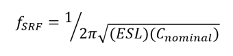
SRF (Series Resonant Frequency) – The series resonant frequency (SRF) occurs when the impedance is at its minimum ESR value and the capacitive reactance is canceled by the ESL. The series resonant frequency is defined as:
SWaP- Critical concerns when designing components or subsystems for RF Microwave applications – Size, weight, and power (SWaP)
TCC – Temperature Coefficient of Capacitance. A measure and specification of the maximum change of capacitance with temperature, over a particular range of the latter. It is usually given in either parts-per-million per degree Centigrade, ppm/0C, or simply as a percentage. Examples are: NP0 (±30 ppm/0C, -55 to +125 0C), X7R (±15%, -55 to +125 0C ), and X5R ((±15%, -55 to +85 0C) .
Variable Capacitors – A Variable Capacitor, also known as a Trimmer Capacitor, is a unit designed for fine adjustments or calibration in RF Circuits. These components enable precise tuning and optimization of electronic circuits. See Understanding Trimmer Capacitors for more information.
VCC – The Voltage Coefficient of Capacitance is the ratio of capacitance values at different applied DC voltages.
Voltage Breakdown – The voltage breakdown of a capacitor [DC and RF] is that applied voltage (DC or RF peak) that causes a specified current to flow. It can manifest in a number of ways, e.g., arc-over in the air, corona near one terminal, “creep” between terminals, internal arcs between electrodes, or internal arcs between electrodes and terminations. It often – but not always – results in permanent destruction of the device.
WVDC – The Working Voltage DC, otherwise known as the “rated voltage” is, generally, the DC voltage a capacitor can be continuously exposed to and not have its principal specifications (e.g., capacitance, dissipation factor, insulation resistance) change by more than particular specified amounts over a specified time period. Certain capacitors, typically Broadband units with X7R or X5R TCCs, may have an additional constraint: that, at their WVDCs, their capacitance remains at or above a specified value.