Thin Film Dual Chip Resistors
Thin Film Dual Chip Resistors
Product Features
-
-
-
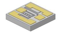
- Two Resistors on a single chip area.
- Available styles are common or isolated node.
- The nature of this design lends itself to tightly matched TCR and electrical tolerance, with resistance rations within 0.01% (value dependent).
- Can be used in Non-Magnetic Applications
-
-


Common Node Configuation


Isolated Node Configuation
Product Specifications
Resistance Range
-
- 2Ω – 1MΩ per resistor (Silicon or Quartz)
- 2Ω – 160kΩ per resistor (Al₂O₃, BeO, AlN)
Resistance Tolerance
-
- ±0.01% to ±20% value dependent
Standard Size
-
- 30 mil x 30 mil x 10 mil
- 0.03″ x 0.03″ x 0.01″
Dual Chip Resistors

Part Numbering
Example PPI Part Number: PDT-35-30×30-10000-20000-AJQK
Resistor Style
Resistive Materials
| Code | Style |
| PD | Common Node |
| PI | Isolated Node |
| Code | Material | Passivation | Sheet Resistivity (Ω/Sq) |
Abs. Tolerance | Ratio Tolerance |
| T | Tantalum Nitride (TaN) |
Self Passivating Ta₂O₅ | 5 to 270 | From ±0.01% | From ±0.01% |
| N | NiChrome (NiCr) |
SiO₂ | 5 to 250 | From ±0.01% | From ±0.01% |
Substrate Materials
| Code | Material | Thickness | Surface Finish | Dielectric Constant (@ 1MHz) |
Coefficient of Thermal Expansion (x10⁶/°C) |
Thermal Conductivity (W/m*K) |
| 35 | Alumina (Al₂O₃) |
0.005″ – 0.010″ | 2μ” – 3μ” | 9.9 | 7 (25°C to <300°C) |
26.9 |
| 28 | Aluminum Nitride (AlN) |
0.005″ – 0.010″ | 6μ” – 8μ” | 8.0 – 9.1 | 4.6 – 5.7 (25°C to <1000°C) |
170 |
| 25 | Beryllium Oxide (BeO) |
0.005″ – 0.010″ | <5μ” | 6.76 | 9 (25°C to <1000°C) |
285 |
| 22 | Silicon (Si) (with 12kÅ SiO₂) |
0.005″ – 0.010″ | Chemical Polish | N/A (SiO₂ K=1.38) |
2.49 – 4.44 (25°C to <1000°C) |
149 (SiO₂ 1.38) |
| 20 | Quartz (Fused Silica) |
0.005″ – 0.010″ | 60/40 Optical Polish |
3.826 | 0.55 (25°C to <1000°C) |
1.38 |
Power Handling Range by Material
| Case Size mils (inches) |
Alumina (35) |
AlN (28) |
BeO (25) |
Silicon (22) |
Quartz (20) |
| 30 x 30 (0.030 x 0.030) |
125 mW | 500 mW | 1.0 W | 125 mW | 25 mW |
Resistance Value
Terminations
Digits 1-4 are significant figures. Digit 5 is the number of zeros to follow. When required, “R” is used as a decimal point and the exponent is ommitted.
Examples:
-
- Code 10001 = 10000Ω
- Code 10000 = 1000Ω
- Code 100R5 = 100.5Ω
| Code | Top Side | Bottom Side | ||
| Metallization | Attachement Options | Metallization | Attachement Options | |
| A | Pd/Au | Wirebond, Non-Cond. Epoxy | – | – |
| R |
Flip Chip (Ti/Pt/Au) |
Cond. Epoxy, Non-Cond. Epoxy, Eutectic Attach Solder | – | – |
| D | Pd/Au | Wirebond, Non-Cond. Epoxy | Ta/Pd/Au | Cond. Epoxy, Non-Cond. Epoxy, Eutectic Attach, Solder |
Resistance Tolerance
Temperature Coefficient
Resistance Ratio
| Code | Tolerance |
| B | ±0.1% |
| D | ±0.5% |
| F | ±1% |
| G | ±2% |
| H | ±3% |
| J | ±5% |
| K | ±10% |
| L | ±15% |
| M | ±20% |
| Q | ±0.05% |
| S | ±0.01% |
| Code | TC | Material | |
| Tantallum Nitride (TaN) |
NiChrome (NiCr) |
||
| Q | ±150PPM/°C | Standard | – |
| V | ±100PPM/°C | Yes | – |
| W | ±50PPM/°C | Yes | Yes |
| X | ±25PPM/°C | – | Standard |
| Y | ±10PPM/°C | – | Yes |
| Z | ±5PPM/°C | – | Yes |
| Code | Tolerance to Other Resistors |
| G | ±0.01% |
| H | ±0.05% |
| J | ±0.10% |
| K | ±0.25% |
| M | ±0.50% |
| N | ±1.00% |
| R | No Ratio |
Packaging
General Properties
Testing
| Code | Style |
| W | Waffle Pack (Standard) |
For additional packaging options, please contact PPI.
| Operating Temperature | -55°C to +150°C |
| Storage Temperature | -65°C to +150°C |
| Operating Frequency | DC to 500 MHz |
| Voltage Rating | 100V maximum |
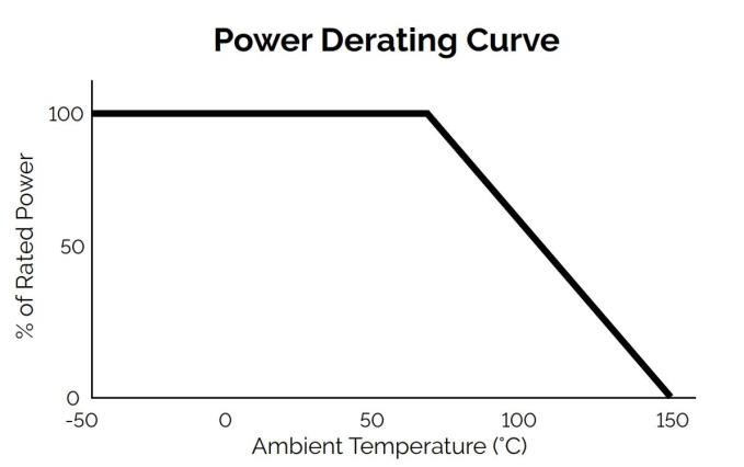
| Power Derating (See Chart below) |
Full power up to 70°C Derated linearly to zero power at 150°C |

| Testing Performed | Specification/Standard |
| Visual Inspection | MIL-PRF-55342 MIL-STD-883 |
| Mechanical Inspection | MIL-PRF-55342 |
| DC Resistance | MIL-PRF-55342 MIL-STD-202 |
| Resistance Temperature Characteristics (TCR) | MIL-PRF-55342 |
| Short Time Overload | MIL-PRF-55342 |
| High Temperature Exposure | MIL-PRF-55342 |
| Thermal Shock | MIL-PRF-55342 MIL-STD-202 |
| Resistance to Bonding Exposure | MIL-PRF-55342 |
| Wire Bonding Integrity | MIL-PRF-55342 |
| Life Test | MIL-PRF-55342 MIL-STD-202 |
Performance Specifications
Higher power ratings, additional sizes, and custom resistors available. Please contact sales@passiveplus.com.
Passive Plus offers a comprehensive range of Thin Film Components, designed to meet the diverse needs of the engineering community. PPI Thin Film Components are Made-to-Order and customized to specific applications. Offering precision, reliability, and customization options that cater to your unique requirements.
PPI Thin Film Components deliver tight tolerances, precision, and reliability for any engineering project. Explore each Thin Film type to determine the perfect fit for your application or contact PPI (sales@passiveplus.com) and our team can work with you to determine the best solution.
Once these specifications are confirmed, PPI will then supply the customer with a Spec Sheet with pricing and delivery options.
Please contact PPI directly at 631-425-0938 or by email at sales@passiveplus.com to start this process.

