 +1 631-425-0938
 Contact
 Search
 C.A.P. Product Lookup
 Translate
Thin Film Spiral Inductors
Thin Film Spiral Inductors
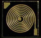
Spiral Inductors consist of thin film gold spiral patterned on a substrate for use in a wide variety of uses, including storing electrical energy in the form of magnetic energy, in frequencies from DC to RF.
An optional polymide coating over the coil is available for increased resistance to scratches or shorts. Non-conductive epoxy is recommended as a mounting method, backside metallization is also available. A second corner pad is provided for easy wire-bonding from the center pad for edge-contact mounting.
Product Features
-
- Low Capacitance
- Less Resistive & Capacitive losses
- RoHS Compliant
Applications
-
- Microwave Circuit Resonant elements
- Electrical Power & Electronic Devices
Product Features
-
- Choking, Blocking, Attenuating, or filtering/smoothing high frequency noise
- Storing & transferring energy in power converters
- Creates tuned oscillators or LC “tank” circuits
- Impedance matching
Thin Film Spiral Inductors
Part Numbering
Example PPI Part Number: PLS20-50x50x10A28R00BW
Substrate Materials
| Code | Material | Thickness | Surface Finish | Dielectric Constant (@ 1MHz) |
Coefficient of Thermal Expansion (x10⁶/°C) |
Thermal Conductivity (W/m*K) |
| 35 | Alumina (Al₂O₃) |
0.005″ – 0.010″ | 2μ” – 3μ” | 9.9 | 7 (25°C to <300°C) |
26.9 |
| 20 | Quartz (Fused Silica) |
0.005″ – 0.010″ | 60/40 Optical Polish |
3.826 | 0.55 (25°C to <1000°C) |
1.38 |
Physical Dimensions
| Case Size (Mils) |
Inductances | # of Turns | DC Resistance | Q (@ 200MHz) |
Q (@ 500MHz) |
| 25 x 25 | 1.2 nH | 1.5 | 0.6Ω | 3 | 7 |
| 25 x 25 | 2.0 nH | 2.0 | 0.9Ω | 3 | 8 |
| 25 x 25 | 3.0 nH | 2.5 | 1.2Ω | 4 | 9 |
| 30 x 30 | 4.4 nH | 3.0 | 1.5Ω | 4 | 10 |
| 30 x 30 | 6.0 nH | 3.5 | 1.9Ω | 4 | 11 |
| 30 x 30 | 7.9 nH | 4.0 | 2.3Ω | 4 | 11 |
| 40 x 40 | 10 nH | 4.5 | 2.7Ω | 5 | 12 |
| 40 x 40 | 13 nH | 5.0 | 3.2Ω | 5 | 12 |
| 40 x 40 | 16 nH | 5.5 | 3.7Ω | 5 | 13 |
| 40 x 40 | 19 nH | 6.0 | 4.2Ω | 6 | 13 |
| 40 x 40 | 23 nH | 6.5 | 4.7Ω | 6 | 14 |
| 50 x 50 | 28 nH | 7.0 | 5.3Ω | 7 | 14 |
All dimensions are in mils.
Metallization Codes
Inductance Codes
| Code | Top Side | Bottom Side | ||
| Metallization | Attachment Options | Metallization | Attachment Options | |
| A | Pd/Au | Wirebond, Non-Cond. Epoxy | – | – |
| D | Pd/Au | Wirebond, Non-Cond. Epoxy | Ta/Pd/Au | Cond. Epoxy, Non-Cond. Epoxy, Eutectic Attach Solder |
| Value | Code |
| < 10nH | 1R50 = 1.5nH |
| > 10nH | 28R0 = 28nH |
| Digits 1-4 are significant figures. The “R” is used as a decimal point |
|
Inductance values are computed in free air, using a magnetic permeability for free air of μ = 4.0 x 10⁻⁷. DC resistance is based on a gold metallization.
Protective Coating
Packaging
| Code | Polymide Coating |
| B | Without Coating |
| P | With Polymide Coating |
| Code | Style |
| W | Waffle Pack (Standard) |
For additional packaging options, please contact PPI.

General Properties
Testing
| Operating Temperature | -55°C to +150°C |
| Storage Temperature | -65°C to +150°C |
| Operating Frequency | DC to 500 MHz |
| Insulation Resistance | 10¹²Ω min at 25°C |
| Testing Performed | Specification/Standard |
| Visual Inspection | MIL-PRF-55342 MIL-STD-883 |
| Mechanical Inspection | MIL-PRF-55342 |
| DC Resistance | MIL-PRF-55342 MIL-STD-202 |
| High Temperature Exposure | MIL-PRF-55342 |
| Thermal Shock | MIL-PRF-55342 MIL-STD-202 |
| Resistance to Bonding Exposure | MIL-PRF-55342 |
| Wire Bonding Integrity | MIL-PRF-55342 |
| Life Test | MIL-PRF-55342 MIL-STD-202 |
Passive Plus offers a comprehensive range of Thin Film Components, designed to meet the diverse needs of the engineering community. PPI Thin Film Components are Made-to-Order and customized to specific applications. Offering precision, reliability, and customization options that cater to your unique requirements.
PPI Thin Film Components deliver tight tolerances, precision, and reliability for any engineering project. Explore each Thin Film type to determine the perfect fit for your application or contact PPI (sales@passiveplus.com) and our team can work with you to determine the best solution.
Once these specifications are confirmed, PPI will then supply the customer with a Spec Sheet with pricing and delivery options.
Please contact PPI directly at 631-425-0938 or by email at sales@passiveplus.com to start this process.
